
dell computer that will not get past power-on-self-test
Dell diagnostics say bad system board
 Your Name
be4d80110c
fix image ref
Your Name
be4d80110c
fix image ref
|
il y a 4 ans | |
|---|---|---|
| boardview | il y a 4 ans | |
| component-datasheets | il y a 4 ans | |
| pictures | il y a 4 ans | |
| .README.md.swp | il y a 4 ans | |
| OptiPlex-Diagnostic-Indicators.pdf | il y a 4 ans | |
| README.md | il y a 4 ans | |
| desktop-optiplex-960-technical-guidebook-en.pdf | il y a 4 ans |
README.md
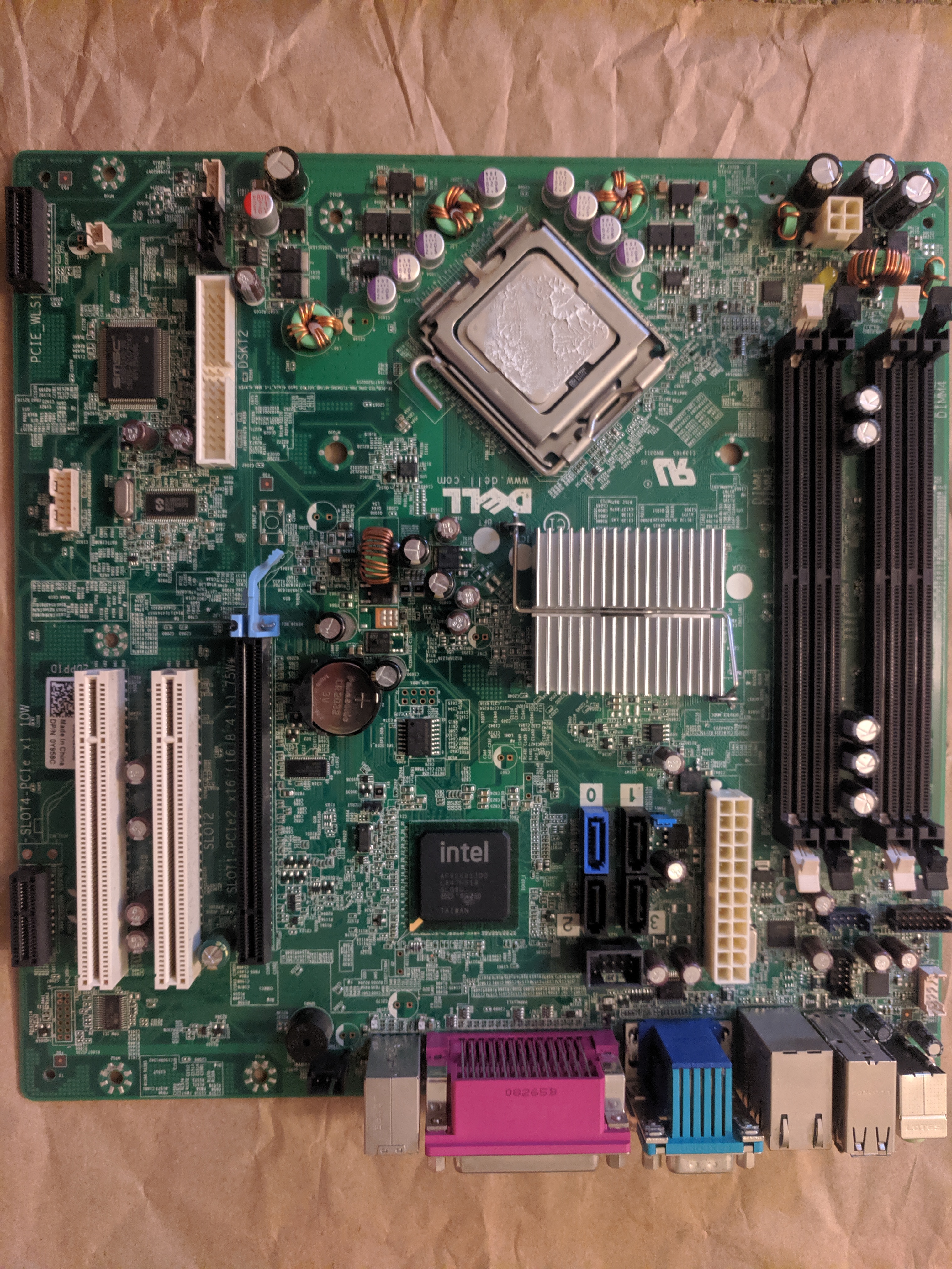
Dell Optiplex 960
Problem
The computer powers up and then powers down.
Initial Inspection
When plugged in the power supply and CPU fan turn on for about 2 seconds then there is a soft metalic tone, like a musical woodblock being struck and the power is turned cut. I think the woodblock sounding noise is just the PSU turning off. The power supply emits an audible high frequency tone when turned on. The CMOS battery was already removed when inspection was started. On a multimeter, without load the VBATT was 2.7 instead of the 3.0. Replacing the CMOS battery with a new one showed no change. The RSTRTC pins were shorted and the PSU was brought out of standby, the CPU fans stayed on. After 5 minutes and no POST the power was removed. Possibly the front panel did not have any indication that there was a problem. Turning on the computer using the power button and the power button led illuminated orange. The 1 and 2 led were blinking, according to Dell this indicates a problem with the system board. All cables were removed from the motherboard and the motherboard was removed from the chassis. The thermal interface between the CPU and heatsink was crusty. The power supply standby pins were shorted and the power rails were measured. Most rails were a little low. I think the 5V rail was 4.6V the 12V rail was 11.4V. The power supply has a "test" button and when pressed the PSU led is lit green, or okay.
A 10 ohm load was placed across the 12V rail and measured. With a load it was 1.8VDC, without 11.4V. That seemed weird.
Some capacitors seemed raised abnormally from the motherboard. They were removed and tested. Two Panasonic 680uF 16V capacitors were tested, when tested with a 1kHz signal they had about 0.01ohms ESR and could hold 570uF. This seemed okay so they were put back into the board.
Other capacitors were removed either because they were not sitting right, or randomly, and in groups. There were some ceramic capacitors that were discolored and had green corrsoion on the pad facing the edge of the board, these were removed and inspected.
Removed Capacitors
- 8 x Panasonic SEPC Aluimnum Poly 820uF - most measured 0.01ohm ESR and above rated capacity, 3 were under 770uF (93% to 107%)
- 4 x Panasonic Matsushita Aluminium Electrolytic 1800uF - all measured about 0.02ohm ESR and all under 1500uF (83%)
- 2 x Nippon Chemi-Con Aluminium Electrolytic 220uF - both measured about 0.15ohm ESR and about 200uF (90%)
- 7 x Nippon Chemi-Con Aluminium Electrolytic 470uF - all measured about 0.17ohm ESR and under 380uF (80%)
- 6 x Ceramic Multilayer unknown - they measured between 19uF and 20uF with an ESR of .16ohm (probably 100%)
- 1 x Fujitsu Aluminium Poly 270uF - measured 250uF and .02ohm ESR
- 2 x Rubycon MCZ Aluminium Electrolytic 1800uF - about .01ohm ESR and under 1550uF (about 86%)
- 5 x Rubycon MCZ Aluminium Electrolytic 820uF - did not measure
- 1 x Sanyo WG Aluminium Electrolytic 470uF - .04ohm ESR and 407uF (86%)
Ordered Replacements For
- The Nippon Chemi-Con capacitors were both 6mm diameter and 12mm tall. The KY series low impedance datasheets suggest that the ESR is in range. The brown wrappers and markings indicate that they are KY series. The modern datasheet did not have the exact capacitors listed. The 470uF were replaced with NIC NRSH471M6.3V6.3X11F. And the 220uF with NIC NRSH221M16V6.3X11F.
- The Panasonic caps are 8mm diameter and 21mm tall. The M series datasheet suggests that 6.3V capacitors that are 20mm tall should be 0.03ohms impedance at 20 degrees Celcius. Replaced with Panasonic EEU-FSoJ182L.
- The purple labled Panasonic SEPC Aluminium Poly caps are 8mm diameter and 9mm tall. They are rated for 2.5V and are either supposed to between .005ohm and .007ohm ESR. Panasonic calls them "organic" capacitors. Replaced with Nichicon RL80G821MDN1KX.
- The red labled Fujitsu branded AlPoly was 8mm x 12mm tall, had markings 8YH and 271, seems rated for 16V. The label is red, Nichocon uses the same style datasheets, but I could not find a matching datasheet. Replaced with Nichicon RNU1C331MDN1KX.
- The big Rubycon near 12V rail, but 6.3V capacitors are 10mm diameter and 16mm tall. The MCZ is a very good series, but does not seem available. Replaced with Aluminium Poly Nichicon PLG0J182MD01.
- The smaller Rubycon between the RAM sockets are 8mm x 12.5mm tall. These are also MCZ, so I found a suitable replacement in the form of Aluminium Polymer. Replaced with Nichicon RL80J821MDN1KX.
- Replaced the 6 unknown MLCC with NIC NMC1210X5R226M25TRPLPF. These measured about 22uF and .018ohm ESR. They seem to be the same size, but they are probably pretty different from the original. Oh well.
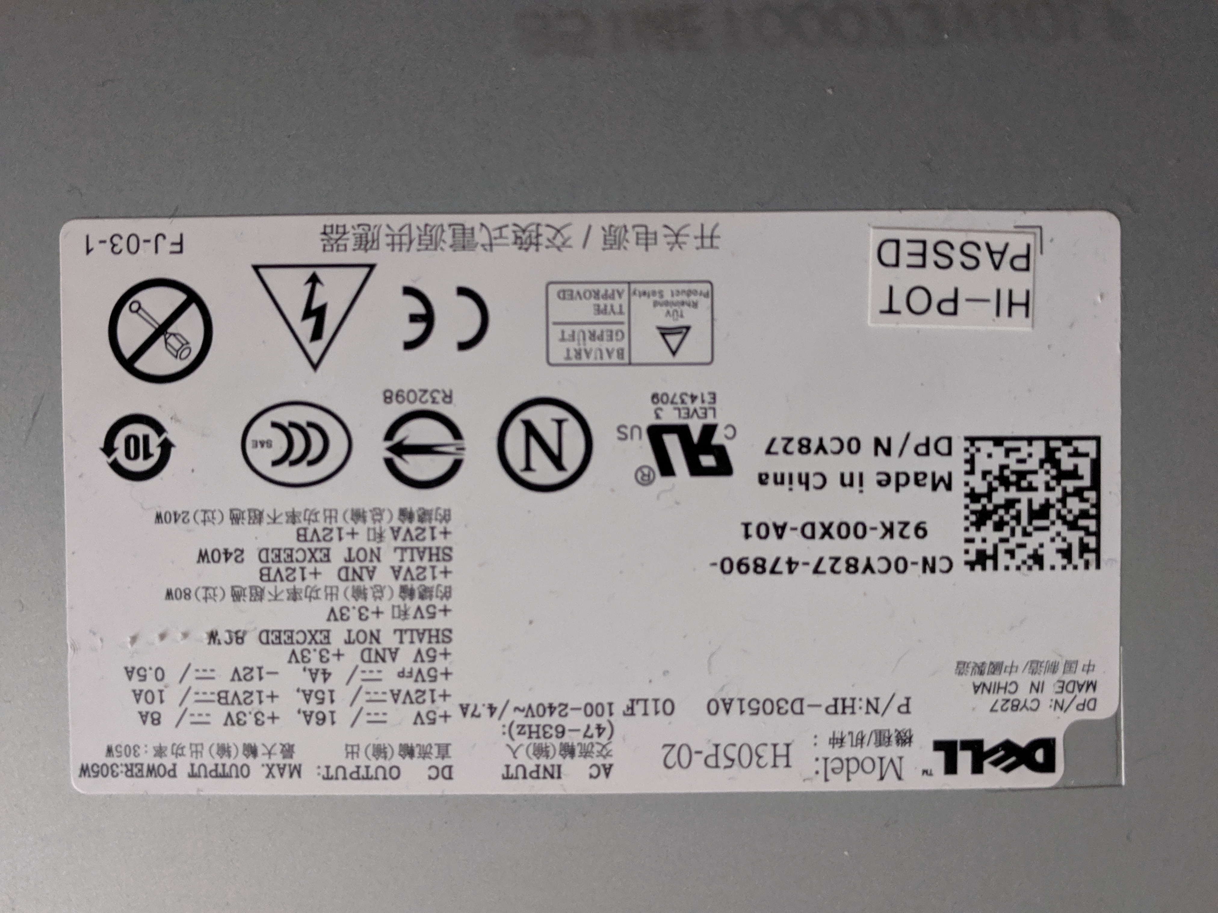
Power Supply
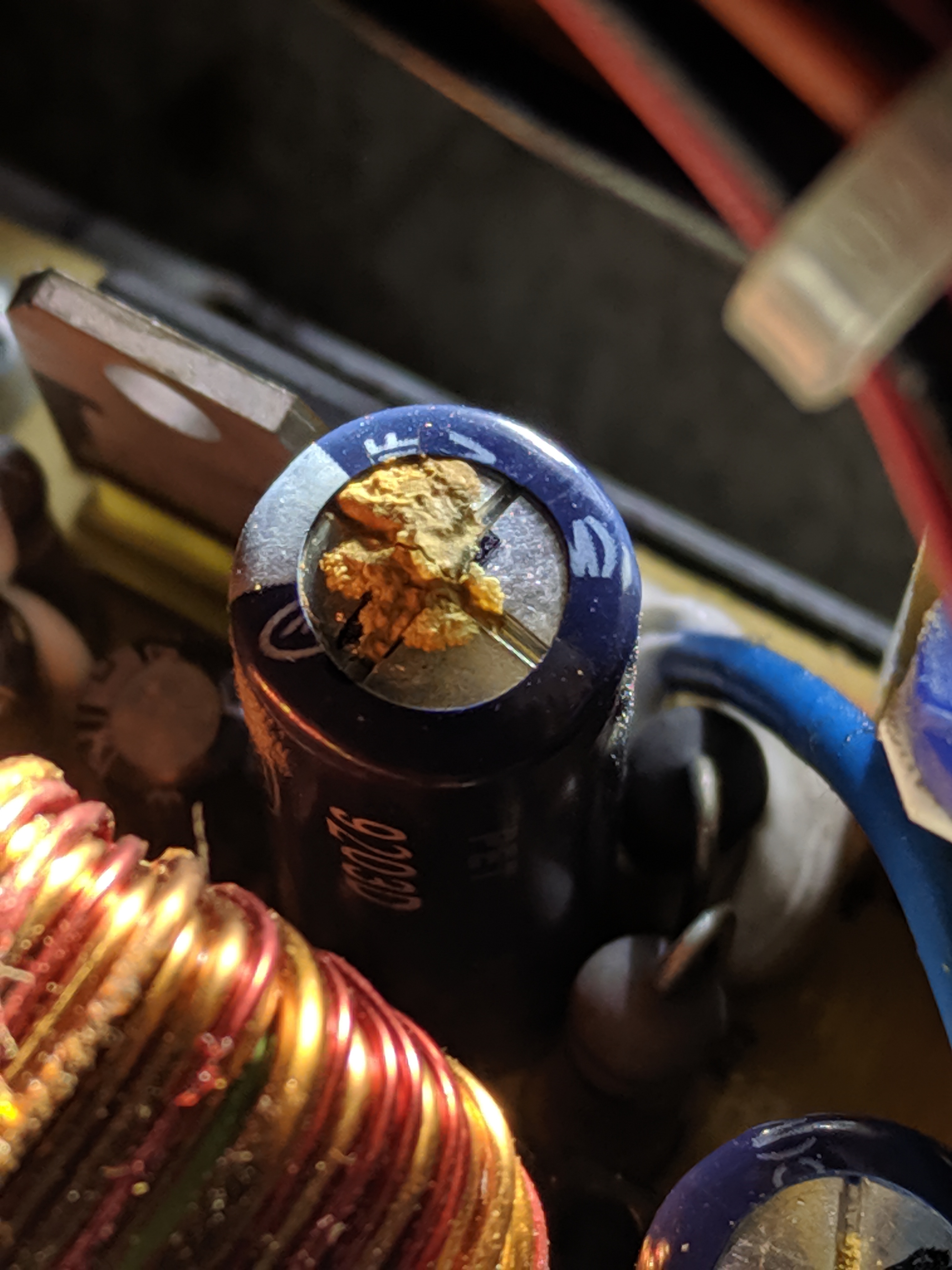
I decided to remove the power supply and look at it. There were at least 2 leaking capacitors on the DC side. There are probably like 10 other caps, visually they look fine, but some are covered in the white silicon stalking goop. The leaky capacitors were the largest caps near the negative 12V linear regulator 7912 IC.
Inspection
Initially I was probing the output DC rails and found a regular ripple. The FFT plot showed a wide bandwidth peak, more like a knoll, centered on 21MHz. I also captured a ringing waveform that had a 3uS tail that seemed to occur about every 13-17uS. I was using the probe's alligator ground lead which may have increased the amplitude of the ripple. I took serveral pictures of what looked to be a 1Vpp ripple on all the rails. It seemed worse on the 12V rail. Later I added the 20MHz bandwidth limit and used a better ground by wrapping a length of wire around the ground ring of the probe so that the ground loop was only 2-3mm in diameter. This time I found the FFT plot showed a small well defined 6kHz peak and another stronger 70kHz peak. I probed around the PSU and found a weird switching waveform with 20V peaks at 70kHz. I did not find the source of the 6kHz signal. I think I can hear it though. It might be the high pitch sound when the supply is running.
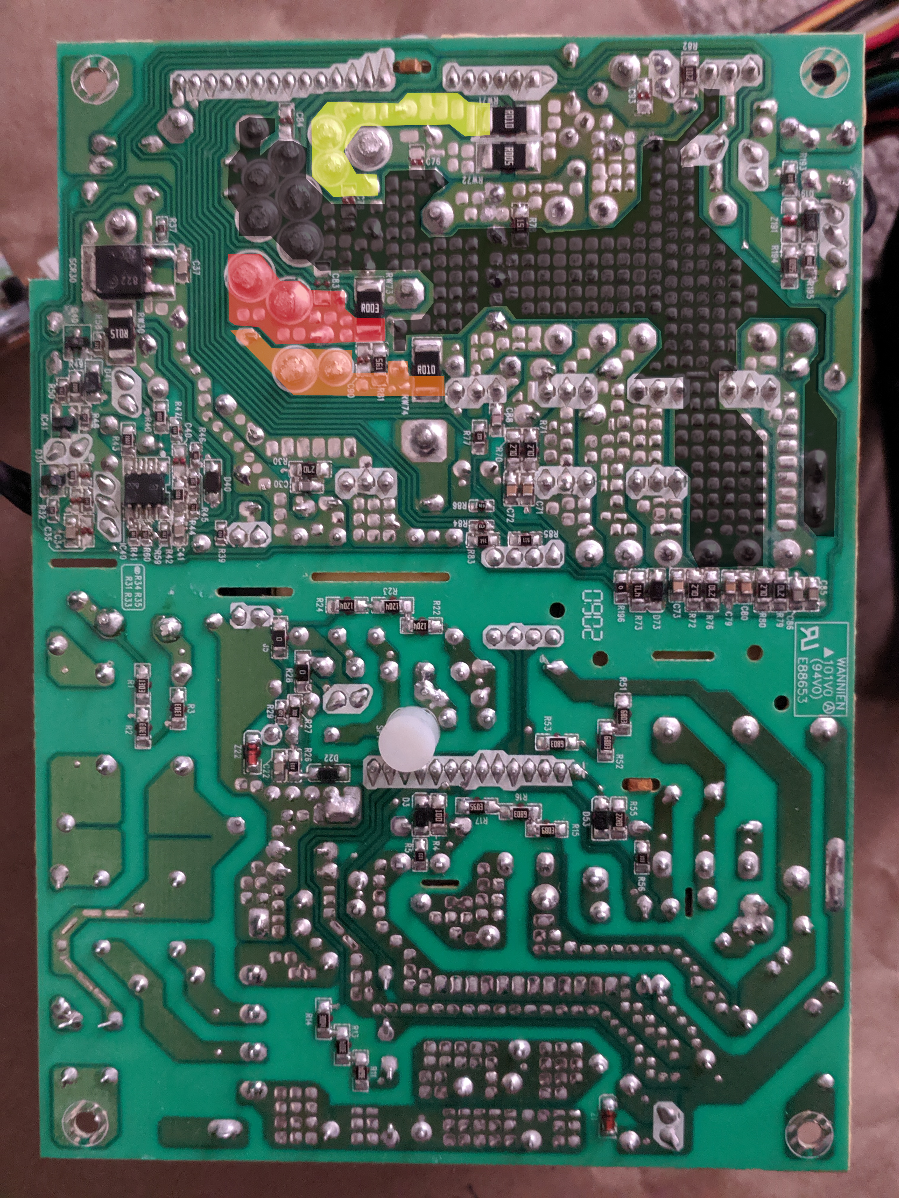
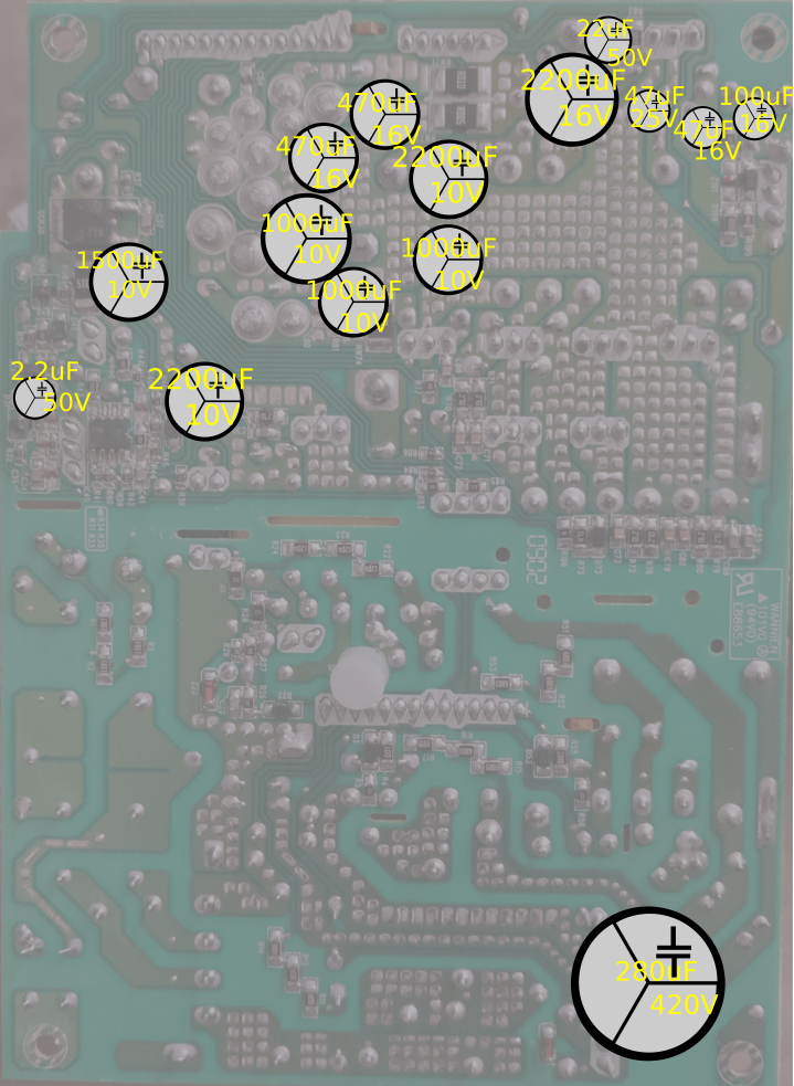
Removed Capacitors
- 1 x Ltec Aluminium Electrolytic 2200uF - C?? - measured 3.2ohm ESR and about 60uF rated at 16V (3%)
- 1 x Ltec Aluminium Electrolytic 2200uF - C81 - measured 2.5ohm ESR and about 50uF rated at 10V (3%)
- 1 x Ltec Aluminium Electrolytic 2200uF - C31 - meter could not measure - rated at 10V
- 1 x Ltec Aluminium Electrolytic 1000uF - C87 - 1.37phm ESR and 10uF rated at 10V (1%)
- 1 x Ltec Aluminium Electrolytic 100uF - C191 - 0.15ohm ESR 90uF rated at 15V (90%)
- 1 x Ltec Aluminium Electrolytic 22uF - C92 - 0.10ohm ESR and 18uF rated at 50V (82%)
- 1 x Ltec Aluminium Electrolytic 1500uF - C36 - .02ohm ESR 1590uF rated at 10V (106%)
- 1 x Elite Aluminium Electrolytic 180uF - C?? - .29ohm ESR 150uF rated at 420V (83%)
Ordered Replacements For
- The 16V Ltec Aliminum 2200uF measured 10mm x 29mm and ware LZP series. I could not find the exact match, but the 10mm x 23mm had an expected ESR of .04ohms. Replaced with Nic NRZJ222M16V12.5X20F.
- The 10V Ltec Aliminum 2200uF measured 10mm x 24mm and ware LZP series. I could not find the exact match, but the 10mm x 23mm had an expected ESR of .036ohms. Replaced with Nic NRZJ222M16V12.5X20F.
- The Ltec 100uF 15V caps measured 7 x 12 LPZ series. Replaced with Panasonic EEU-FR1C221 220uF.
- The Ltec 1000uF 16V caps measured 8 x 16 LPZ series. Replaced with Nic NRZJ102M16V10X16F.
- The Elite 180uF 420V input bulk capacitor is 180uF 420V 18mm and 50mm tall. Replaced with EKXJ451ELL121MM40S.
Have not ordered replacements
The Ltec 1000uF 16V caps measured 8 x 16 LPZ series but replaced with the Nic NRZJ102M16V10X16F. The Ltec 22uF 50V caps measured 5 x 12 LPZ series but replaced with a Panasonic FR 22uF 50V. The Ltec 2.2uF 50V caps measured 5 x 12 LPZ series but replaced with a Panasonic FR 22uF 50V. The Ltec 1500uF 10V caps measured 10 x 24 LXY series but replaced with the Nic NRZJ222M16V12.5X20F.
Repair
When I actually did the repair I ended up pulling all the DC side capacitors. There was a passive PFC board that I did not touch, and the switching section was also left alone. Everything was replaced and the 5 or so caps that I did not order parts for I replaced with similar at least the volt rating and usually double the capacitance. There were two sections where I replaced with capacitors that were too big and the caps in those areas ended up wonky.
Completed
The PSU from Wes arrived after many of the difficult to remove caps had been pulled from the motherboard. There were no caps on the motherboard that seemed especially bad. After the replacement capacitors arrived all the new caps were installed and the computer was powered up with Wesley's PSU. The blue power led lit indicating a successful POST. At this point the bad power supply was connected to the motherboard. The computer booted fine. The leaking capacitors, and all other DC output capacitors were removed and replaced. The modified powersupply was tested with the motherboard, it too powered up with a blue indicator led. It is unknown if repairs on just the original power supply would have fixed the problem or if both motherboard and power supply participated in causing the computer to no POST.
On 2020 October 17th the computer was returned to Martin.